GPR survey processing using OpendTect

J.-M Friedt, Aug.2, 2022

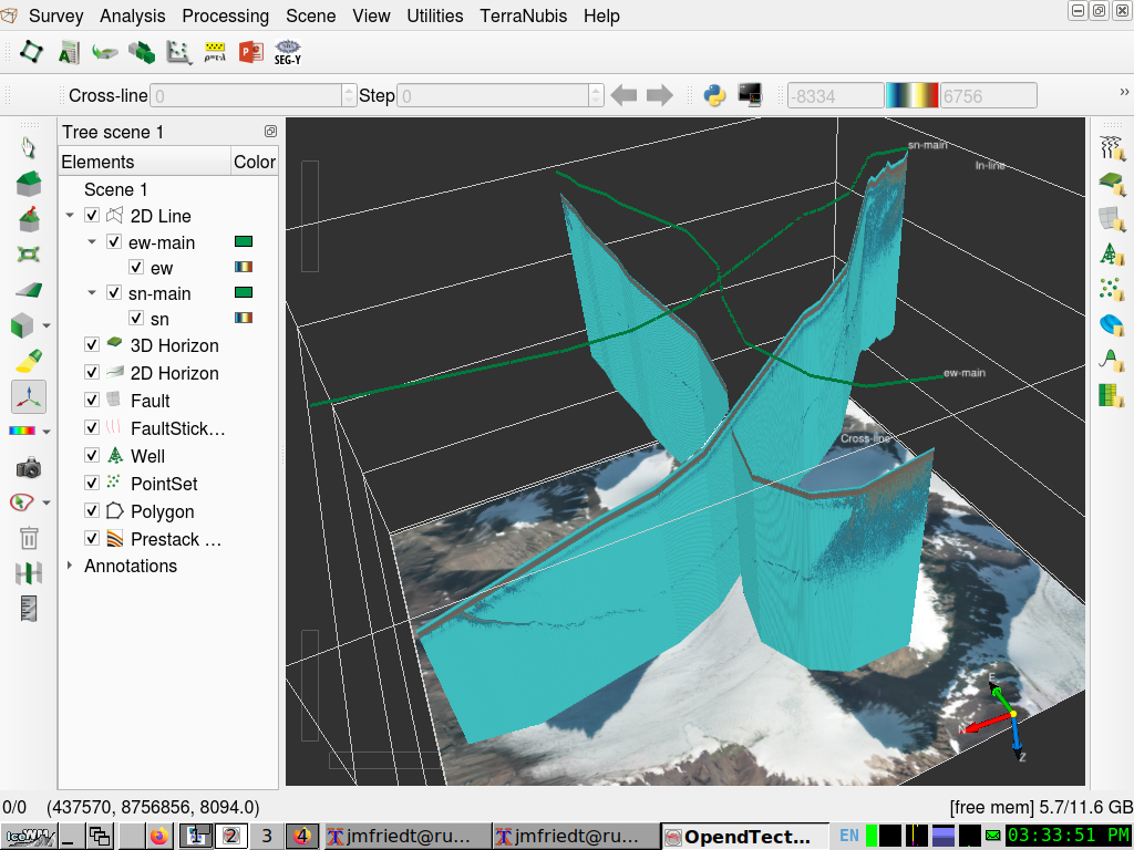
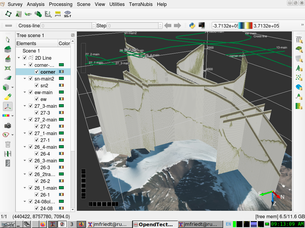
We have demonstrated the ability to read an ASCII file with each line starting with the WGS84/UTM coordinates in OpendTect as 2D GPS B-scans to be displayed in 3D along their acquisition track. Doing so assumed a flat terrain (constant datum) and the topography was not resolved. Here we aim at

  1. use SEG-Y format in an attempt to use some of the parameters of the header to shift the datum. Although using the header to shift the traces will fail, using SEG-Y instead of ASCII as advised by OpendTect is satisfactory
  2. insert dummy samples at the beginning of the traces to shift their origin and represent topography. We have discovered that filling these cells with NaN leads to transparency
First the ASCII records are converted to SEG-Y binary files and each header is filled with the Common Mod-Point (cdp) coordinate (cdpX,cdpY). This will be achieved using segymat (release 1.6). Then the resulting SEG-Y files are loaded in OpendTect, validating the automated generation of the Survey by reading the SEG-Y header or manually defining the Survey. Finally, the projected B-Scans are displayed in their geographical context.
  1. The ASCII files holding the measurements are 4095 columns and as many lines as traces that were collected. They are readily loaded in GNU/Octave using the load command and will provide the basic data to generate the SEG-Y file. Furthermore, it is assumed that two files were created from the GPS records (GPX loaded into QGis as WGS84 coordinates and saved as WGS84/UTM33N -- make sure to select Export -> Save Feature As -> Layer Options -> Geometry as AS_XY to output the new CRS), one with the geographic position (X,Y) named pos and one with the elevation named ele.
  2. We load the ASCII array of measurements, position and elevation, saved the relevant indices of the GPS track where the trace departs from a straight line, and interpolate between these features to avoid noise in the GPS measurements
    ffs=1000;   % dummy sampling rate
    fs=1518.67; % GPR sampling rate Hz 
    addpath('../segymat-1.6/');
    pos=load('ew.pos33N'); % load trace position
    ele=load('ew.ele');    % load elevation
    maxele=max(ele);
    dl=dir('ew-main');     % load GPR B-scan dataset 
    x=load(dl.name);
    X=[];
    Y=[];
    Z=[];                  % below the index of the GPX trace and their (X,Y) coordinates
    indn=[103     464     719     1119    1610    2045    2642    3616    3831    4316    4523    4771    ] % QGis GPS indices
    indx=[437551  437641  437801  438139  438521  438819  439256  439817  439975  440234  440378  440534  ] % QGis GPS indices
    indy=[8756744 8757006 8757135 8757230 8757142 8757018 8756983 8757137 8757149 8757235 8757239 8757279 ] % QGis GPS indices
    for dnn=1:length(indn)-1
         X=[X linspace(pos(indn(dnn),1),pos(indn(dnn+1),1),round(size(x)(1)*(indn(dnn+1)-indn(dnn))/(indn(end)-indn(1))))];
         Y=[Y linspace(pos(indn(dnn),2),pos(indn(dnn+1),2),round(size(x)(1)*(indn(dnn+1)-indn(dnn))/(indn(end)-indn(1))))];
         Z=[Z linspace(ele(indn(dnn))  ,ele(indn(dnn+1)),  round(size(x)(1)*(indn(dnn+1)-indn(dnn))/(indn(end)-indn(1))))];
         length(X)
    end
    Z=-(Z-max(maxele));
    Z=Z*2; % Two Way trip
    sortie=zeros(size(x)(1),size(x)(2)+floor(max(Z)*fs/300)); % output array
    for k=1:size(x)(1)
       sortie(k,1:round(fs/300*Z(k)))=NaN;                    % prefix with starting point index
       sortie(k,round(fs/300*Z(k))+[1:size(x)(2)])=x(k,:);    % then the trace
       if (round(fs/300*Z(k))+size(x)(2)+1<size(sortie)(2)) % and finally the bottom part (notice we had to escape < for HTML)
          sortie(k,round(fs/300*Z(k))+size(x)(2)+1:size(sortie)(2))=NaN;
       end
    end
    nomsegy=[dl.name,".segy"]
    WriteSegy(nomsegy,sortie','dt',1/ffs,'cdpX',round(X),'cdpY',round(Y),'Inline3D',[0:size(sortie)(1)-1],'Crossline3D',zeros(1,size(sortie)(1)),'revision',1);
    imagesc(sortie(1:3:end,1:3:end)')
    
  3. We have saved the position as cdpX and cdpY. Notice that segytomat will not save any other parameter from the header even if requested to. We modified segymat-1.6/WriteSegy.m with
    if exist('LagTimeA')==1,SegyTraceHeader.LagTimeA = LagTimeA(i);end
    if exist('SourceDatumElevation')==1,SegyTraceHeader.SourceDatumElevation = SourceDatumElevation(i);end
    if exist('ReceiverDatumElevation')==1,SegyTraceHeader.ReceiverDatumElevation= ReceiverDatumElevation(i);end
    
    but if these parameters are read, they are not used by OpendTect to shift the traces. LagTimeA was detected and provided as argument when reading the Seg-Y file but did not change the display.
  4. Now that the SEG-Y file has been created, launch OpendTect and define a new survey, either as before with In-line and Cross-Line ranging from 0 to 1 and the coordinate transform defining (0,0) as the (X,Y) position of the left corner in WGS84/UTM coordinates, (0,1) the top-left and (1,0) the bottom-right (X,Y) coordinates.
  5. Alternatively, we have checked that defining the Survey geometry by reading the SEG-Y file works and (cdpX,cdpY) is properly identified, but we had to manually select Inline Range and Cross-line Range both to "tracr (byte 5)" ranging from 1 to the number of traces. Then the conversion to the geographical coordinate system was properly identified.
  6. Load the SEG-Y with Survey -> Import -> Seismic Data -> SEG-Y -> Line(s). Same story as above, set Trace Number Range and Shotpoint Number Range as Tracer (byte 5), then Copy Data and give an Output 2D Data (attribute) name
  7. Finally 2D Line -> Add... and select the trace that was just included
  8. Repeat for all B-scan, add the underlying map as before with Scene1 (right click) -> Top/Bottom images
The result is as follows:


After including all GPR processing steps (removal of the mean value of each A-scan, band-pass filter and thresholding) and adding all collected traces my computer can handle, the result is